Amir B. Tabrizia, Robert Markoskib
a Mechanical Engineer, International Mining Engineering Consultants (IMEC), Perth, WA, Australia
b Engineering Manager, International Mining Engineering Consultants (IMEC), Perth, WA, Australia
Abstract
The mining sector in Australia consumes approximately 500 petajoules per year, which is 10% of Australia’s total energy usage. It is predicted that the Australian mining sector’s long-term energy intensity will see a year-on-year increase in usage due to the trending decline (on average) of ore grades, which requires mines to remove more waste (overburden) for sustained mineral output. Wind and solar are primarily considered the main renewable resources which can be effectively utilized by the mining sector to generate power, However, given the use of water systems within underground mines another source of renewables in the form of small hydropower may provide a ‘green generation method’ not typically considered and is discussed in this paper.
Common practice for underground mines is to utilise ‘Break Tanks’ in the supply water system from surface to the network underground which is utilized throughout the mine operation. The Break Tanks control the piping system pressure that continues to increase with depth due to gravity. The Break Tank do this by simply ‘breaking’ the pipework distribution system back to atmospheric pressure. Instead of ‘losing’ this energy generated by gravity, it has been estimated that by installing a pump as a Turbine (PaT) at the inlet of the Break Tank, up to 300 kW of energy could be recovered (in a typical Australian underground mine operation), which annually generates up to 2.5 GWh electricity which translates to savings of up to AU$ 0.7 million of mine site annual electricity costs and reduces CO2 emissions (assuming the mine power is hydrocarbon generated). In addition to several hydraulic advantages of utilizing Break Tanks in an underground mine water supply system, energy recovery is another benefit which should be considered as well.
Keywords: Underground Mining, Renewable Energy, Break Tank, Pump as Turbine (PaT)
- Introduction
The mining sector in Australian consumes around 500 petajoules per year which is 10% of Australia’s total energy usage. As mining volumes increase in Australia, the mining sectors electricity consumption has risen approximately 6.0% per annum over the last decade [1,2].
Diesel (41%), natural gas (33%), and grid electricity (22%), are the main energy sources which generate electricity for Australia’s mining sector while a mixture of other refined fuels, biofuels, renewables, LPG and coal contribute the remaining energy sources for electrical power generation in the mining sector [3]. Over the past decade, diesel contribution has reduced from 49% to 41%, and has been significantly replaced by grid electricity and natural gas due to infrastructure developments and volatility of the oil prices [2].
It is predicted that the Australian mining sector’s long-term energy intensity will continue to increase due to the average falling ore grades (close to surface) and overburden increasing (over the last 30 years, the average grade has halved, and overburden doubled) [4].
Development of batteries and electric equipment has enabled diesel consumed on mine sites to be reduced and increasingly be swapped for a combination of electricity generation and energy storage. It is expected that electricity generation and storage in the mining sector will be more important due to the transition to ‘all electric’ mining. Historically, the “favored fuel source” of Australian mining sector was diesel along with natural gas, however the concept of an ‘all-electric mining’ integrating renewables, batteries and traditional energy is now rapidly building momentum [2].
Logistics and fossil fuel price volatility are outside the control of most mine owners but have a remarkable impact on the economic ability of the mining sector. The mining sector in Australia and the Australian Government have acknowledged the environmental impacts and risk of the fossil fuels and are encouraging the renewable electricity adoption and energy efficiency measures [2]. The Australian mining sector has recently discovered that there is a cleaner, cheaper, and smarter way to power their operations, and the mining industry is now appearing as the source of the next boom in renewables investment [5].
In general, energy storage is currently uncompetitive with fossil fuels for most energy shifting applications. However, the electric vehicles and global attention of renewable energies has led to remarkable research and development in the storage field. It is forecasted that the capital costs of most storage technologies will fall by around 25%–50% over the next 5 years due to improvements of design and chemistry, manufacturing scale and reduction of material costs [2].
As mentioned, wind and solar have been considered as main renewable resources which can be utilized by the mining sector in Australia to generate power. This work discuses another source of renewables, small hydropower, which could be an alternative renewable source for hybrid electricity systems at underground mines in Australia.
- Water supply system of underground mines and available hydro-energy
The water supply system within underground mines is generally very similar throughout Australia. In general, the reticulation of raw water from surface to underground is distributed via a gravity fed system. The layout of the system typically is;
- A Supply System, often in the form of a header tank above ground, which functions either via gravity or is pumped into the mine.
- An Underground Bulk Storage System, to store water in the event of upstream supply problems as well as manage peak demand spikes, and
- A Distribution system, often just standard HDPE pipelines, throughout the mine, with “Break Tanks” and/or pressure reduction valves strategically placed to manage both the pressure the system produces (due to differential static heads), as well as manage localised supply demands (in the case of a break tank).
Given the water is transferred via gravity, the deeper it travels into a mine the more the pressure increases within the pipe system. For the safety of workers and equipment that utilize the water, in addition to the capacity of the piping components, pressure must be maintained within a set range.
For this reason (control of pressure), pressure reduction valves (PRVs) are installed in various locations throughout the mine, with Break Tanks serving a similar purpose (system break back to atmospheric pressure).
As the main supply HDPE lines are extended down the decline, take-offs to the various levels within the mine then tee off. Generally, the system is depicted as per the schematic below:
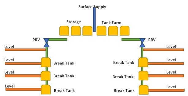
Figure 1 – Generalised Water Supply Schematic of an Underground Mine
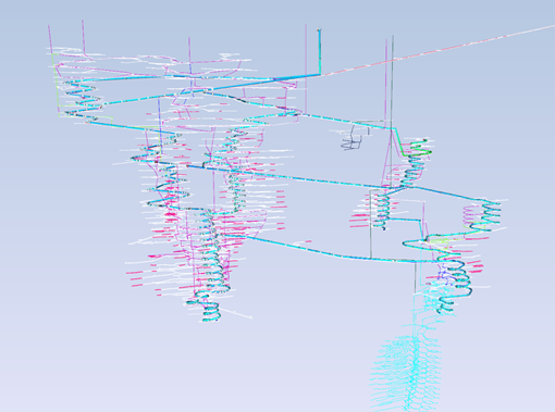
Figure 2 – Isometric View of Water Supply System Model at Underground Mine, Western Australia
It is commonly recommended by professionals that open to atmosphere ‘Break Tanks’ be utilized as pressure reduction equipment for water supply systems at underground mines. These tanks serve as pressure reset devices, as they ‘break’ the pipelines into individual segments and allow the piping network to be exposed to the atmosphere. Further, they provide localized surge capacity within their proximity, allowing for short bursts of high demand to be managed by the tank itself. Installing level-controlled break tanks, every 80-120m vertically, connected via 100mm diameter HDPE lines, is common and generally good practice for water supply systems.
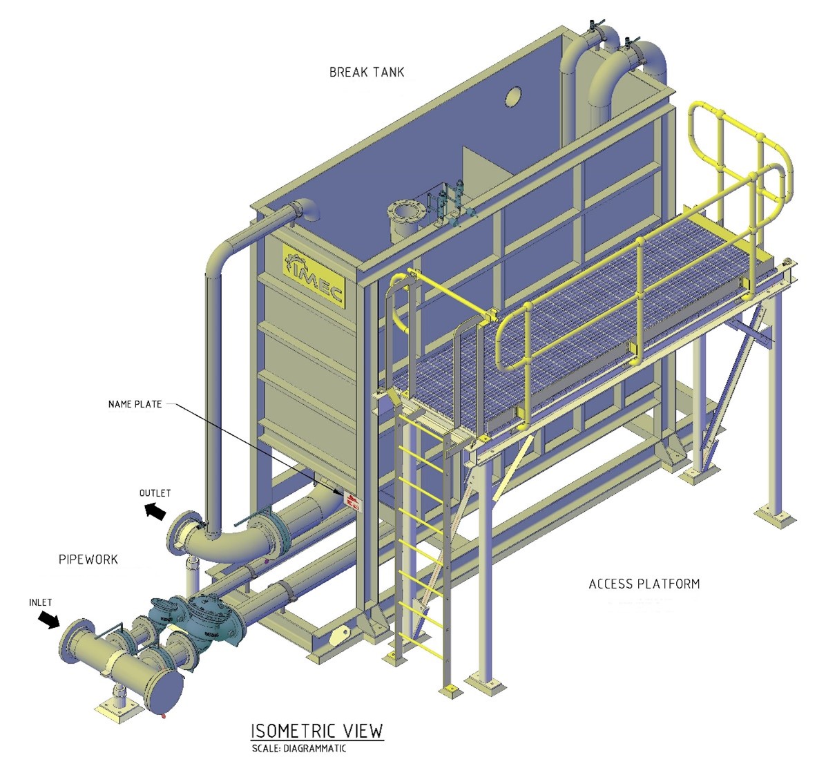
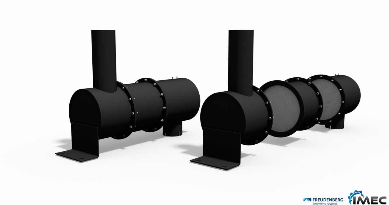
Figure 3 – Typical Break Tank Isometric View (designed by IMEC)
If we assume that the Break Tanks are connected via OD 110 PN 12.5 HDPE pipe, which is very common in underground mining owing to it being manageable size to handle (and comes in large 100m rolls), then based upon the pipe working pressure, the Break Tanks can be located every 120m vertically.
As the pipe route at an underground mine usually follows the haulages, the pipe physical length between every two tanks will be much longer than the 120m vertical height and could be expanded up to 800m (for a typical 1:7 gradient). The level of the water inside each tank usually is controlled using float-level control valves.
Figure 4 shows the pressure loss through a OD110 PN 12.5 HDPE line (100m pipe) across various flowrates which are calculated using the Darcy-Weisbach equation, where Darcy friction factors are obtained from the Colebrook equation approximations suggested by Cheng [9]. If the example static differential head of 120m is assumed between two break tanks, in excess of 40 L/s can be delivered to the downstream break tank during filling time.
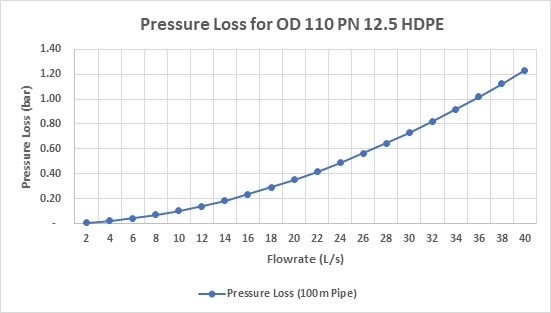
Figure 4 – Pressure Loss through OD110 PN 12.5 HDPE Lines
Typically the break tanks will continue to recharge with water once the low set-point on the float valve is reached, and so flow through the valve will generally be lower than the rates shown above. But in essence, the valve will ‘throttle flow’ into the tank and therefore lose energy via water movement, noise, heat or other means as water fills into the tank and pressure reduces back to atmosphere. Therefore, part of the available head at the tank inlet ccould be exploited as energy via deploying energy recovery devices at the inlet of each Break Tank.
The available energy at the inlet of each tank is calculated from below equation:
E = p x g x Q x h
Where,

Table 1 presents the available energy at the inlet of the downstream tank for different flowrates (using the 120m and 110 OD pipe sizing).
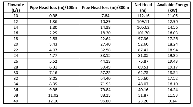
By deploying an energy recovery device at the inlet of each Break Tank, with a duty point of approximately 25 L/s and 79 m Head, the maximum energy can be exploited during filling time, whilst also delivering 25 L/s of water to the tank.
3. Hydro Turbines Vs. Pump as Turbine (PaT) for hydro-energy recovery
As discussed in the previous section, an energy recovery device with duty point around 25 L/s and 79 m Head is required at the inlet of each Break Tank to recover maximum energy.
Figure 5 shows the general operational range of different types of hydro-turbines, Pelton, Francis and Kaplan turbines, for small and mini hydropower solutions.
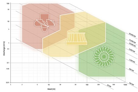
Figure 5 – Operational Range of Different Types of Hydro-Turbine for Small and Mini Hydropower Solutions [10]
In general, the Pelton turbine is utilized for high-head, low-flow application. As the hydro-turbine chart at Figure 5 shows, the Pelton turbine cannot meet the duty point which is required at the inlet of the Break Tank (flowrate=25 L/s and Head=79m).
Pump as Turbine (PaT) technology is taking the field in different small-hydro energy recovery solutions [11]. Williams [12] discussed economic and practical advantages of utilizing PaTs instead of micro hydro turbines in medium-head sites. Due to the possibility of PaTs application in different situations and to its lower cost than turbines, this technology has been rapidly improved in the recent decade [11].
Larger operation range of heads and flowrates, low investment costs, variable installation possibilities, extensive range of products and materials, easier availability of spare parts like seals, bearings and easier installation can be summarized as some advantages of using PaTs instead of micro hydropower turbines [13,14].
In most cases, it is possible for PaT systems to achieve the same high level of pump efficiency in conventional operations. The efficiency of a double-entry volute casing pump is approximately 85 %. At Best Efficiency Point (BEP), the PaT runs as smoothly as a pump in conventional mode. The outgoing flow is almost vortex-free, and noise, wear and pipe vibration are very low [15].
Figure 6 presents a range of different pumps for PaT applications. According to the required operational range at the inlet of the Break Tank (flowrate=25 L/s and Head=79m) Radial Flow PaT or Multistage Radial Flow PaT may be used.

Figure 6 – Choice of pumps for PaT applications [16]
- Economical Evaluation
As explained in section 2, the maximum available capacity of hydropower at inlet of a Break Tank is around 19.5 kW. By taking into account the PaT efficiency (70%) and generator efficiency (95%), the maximum achievable capacity is around 12.95 kW.
The PaT utilized at the inlet of the Break Tank only generates electricity during tank filling. Most of the underground mines, especially the gold mines, in Australia operates 24 hours per day, 365 days per year. However, filling duration of a Break Tank during a day can be varied and depend on activities at different parts of the mine. Figure 7 shows the possible annual generated electricity (365 days of mine operation) by a PaT at the inlet of a Break Tank for different tank filling durations per day.
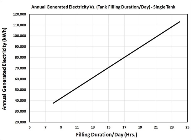
Figure 7 – Possible Annual Generated Electricity by a PaT at Inlet of a Break Tank
The potential saving of electricity costs by using PaT at the inlet of a Break Tank is totally dependent on the electricity price being paid by the mine. The price ranges of <$0.10/kWh for grid electricity, $0.10/kWh–$0.30/kWh for electricity derived from pipeline gas, and $0.15/kWh–$0.30/kWh (after rebates) for electricity generated by off-grid diesel or gas, have been reported as the electricity prices in Australia by the Australian Renewable Energy Agency(ARENA) [2]. Maximum annual saving of mine electricity costs can be achieved by using PaT at the inlet of a Break Tank for the mines which are powered by different sources has been reported at Figure 8.
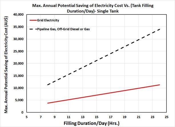
Figure 8 – Maximum Annual Saving of Mine Electricity Cost by Using PaT at Inlet of a Break Tank
Figure 7 and Figure 8 show the annual generated electricity and annual cost saving which is achievable by a single (1) Break Tank. It is common for a mine to utilize multiple tanks, and in some cases upto 15 to 25 Break Tanks for larger/deeper mines. Therefore, by using PaT at the inlet of all Break Tanks, the maximum available capacity of hydropower in an underground mine could range between 195 kW to 325 kW. Annual generated electricity by small hydropower and maximum annual saving on electricity costs in an underground mine would then be increased up to 2.5 GWh and AU$0.7 million, respectively.
Hydropower at the inlet of the break tank is the intermittent source. This limitation can be overcome by utilizing a hybrid system or energy storage. To calculate the payback ratio (period) for utilizing PaT at the inlet of a Break Tank, the cost of battery storage to store the generated electricity for one day with 80% depth of discharge and 1.05 inefficiency factor, has been considered as upfront investment costs as well.
In 2019, battery prices have fallen 87% in real terms to US$156/kWh, while they were above US$1,100 per kilowatt-hour in 2010. According to the latest forecast from research company BloombergNEF (BNEF), average prices will be close to US$100/kWh by 2023. It looks very promising that the price will be reduced even further, from US$100/kWh down to US$61/kWh by 2030 [17].
Table 2 represents the investment cost for utilizing a proper PaT, which was explained in section 2, at the inlet of a single Break Tank.
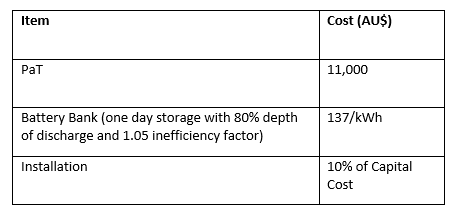 Table 2 – Investment Cost for Utilizing PaT at Inlet of Single Break Tank
Figure 9 shows the minimum payback ratio for utilizing the PaT system including the battery bank at the inlet of a single Break Tank versus different tank filling durations per day for the mines which are powered by different sources.
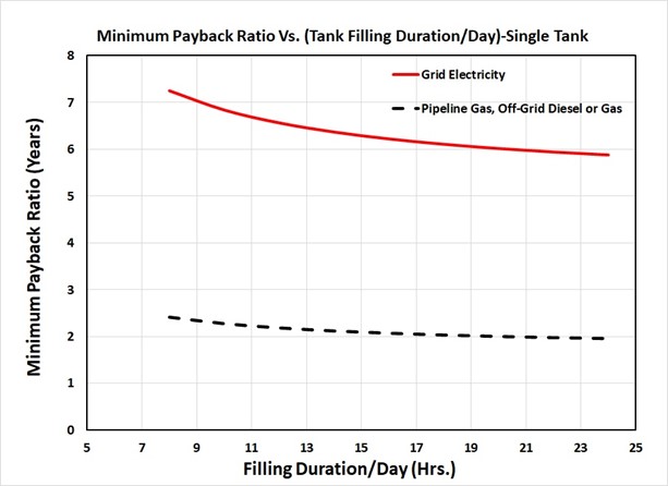
Figure 9 – Minimum Payback Ratio for Utilizing PaT System at Inlet of Single Break Tank Vs. Different Tank Filling Durations Per Day
While the payback ratio is around 2 years for the mines powered by pipeline gas or off-grid diesel/gas, it is around 6.5 years for the mines connected to the grids. However, in future years by dropping the battery price, the payback ratio should be much less than the values reported in figure 9.
- Environmental Advantages
Figure 10 shows the specific carbon dioxide emissions of various fuels and Table 3 represents emission factors for consumption of purchased electricity or loss of electricity from the different grids across Australia.
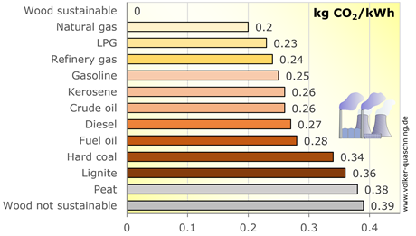
Figure 10 – Specific Carbon Dioxide Emissions of Various Fuels [18]
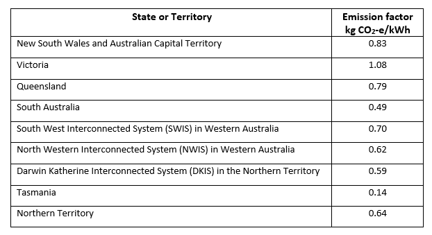
Table 3 – Indirect Emission Factors for Consumption of Purchased Electricity from Different Grids across Australia [19]
Based on the reported values at Figure 7 and Table 3, Figure 8 represents that the annual CO2 emission reduction can be achieved by recovering hydro-energy at the inlet of a single Break Tank at mines which are powered by different grids across Australia or other off-grid systems.
It is notable that Figure 8 reports CO2 emission reduction just for single Break Tank and as explained previously, water supply system of an underground mine usually includes 15 to 25 of Break Tanks.
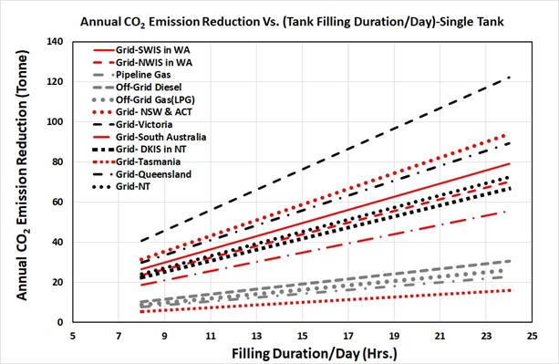
Figure 11 – Annual CO2 Emission Reduction by Recovering Hydro-Energy at Inlet of Single Break Tank
- Conclusion
Wind and solar have been considered as the main renewable resources which can be utilized by the mining sector in Australia. However, small hydropower is another source of renewable energy that can generate electricity for underground mines in Australia.
Utilization of Break Tanks at water supply systems of underground mines is a recommended practice. Installing PaT systems at the inlet of the Break Tanks require low upfront investment costs, can recover more than 300 kW energy, annually generates up to 2.5 GWh electricity and save up to AU$ 0.7 million in annual electricity costs for an underground mine in Australia.
In addition to several hydraulic advantages of utilizing Break Tanks in an underground mine water supply system, energy recovery is another benefit which should be considered as well. As electricity generation and storage in the mining sector is going to be more important due to the transition to ‘all electric’ mining, all available sources to power the mining sector are getting more valuable. Utilizing the Break Tanks as part of an underground mine water supply system, provides an extra source of energy for underground mines. In the close future, by rapid development of battery storage and hybrid power system technologies, utilizing a PaT at the inlet of the Break Tank may be a common practice in underground mining.
References
[1] Australian Government Department of Industry, Innovation and Science, 2016, Australian Energy Update 2016, Canberra, September.
[2] Australian Renewable Energy Agency (ARENA), 2017, Renewable Energy in the Australian Mining Sector White Paper (20062017 Rev. 2).
[3] Australian Bureau of Statistics, 2017, Energy Account Australia 2014-2015 (4604.0).
[4] Bye, A. R., 2011, Case Studies Demonstrating Value from Geo-metallurgy Initiatives, 1st AusIMM International Geo-metallurgy Conference (GeoMet 2011).
[5] https://reneweconomy.com.au/miners-see-50-renewables-as-standard-but-are-aiming-for-100-100/ (Visited on 31/08/2020)
[6] https://www.australianmining.com.au/features/renewables-are-a-no-brainer-for-the-australian-mining-sector/ (Visited on 31/08/2020)
[7] Lazard, 2016, Levelized cost of energy analysis – version 10.0.
[8] Liebreich, M., 2016, Bloomberg New Energy Finance Summit – In search of the miraculous, 5/4/2016.
[9] Cheng N., Formulas for Friction Factor in Transitional Regimes, Journal of Hydraulic Engineering 134 (2008) 1357–1362.
[10] ANDRITZ HYDRO Gmbh, Small and Mini Hydropower Solutions Booklet (available from: https://www.andritz.com/resource/blob/33446/d2118386d6a8dbbec556c6e159391c64/hy-small-and-mini-hydropower-solutions-en-data.pdf)
[11] Rossi M., Righetti M., Renzi M., Pump-as-Turbine for Energy Recovery Applications: The Case Study of An Aqueduct, Energy Procedia 101 (2016) 1207 – 1214.
[12] Williams A., Pumps as Turbines for Low Cost Micro Hydro Power, Renewable Energy 9 (1996) 1227-1234.
[13] Agarwal T., Review of Pump as Turbine (PaT) for Micro-Hydropower, International Journal of Emerging Technology and Advanced Engineering 2 (2012) issue 11.
[14] ANDRITZ Gmbh, Pumps Used as Turbines Booklet ( available from: https://www.andritz.com/resource/blob/238812/7dbb1b203bbd97d0e3740faf76f40f25/pumps-as-turbines-en-data.pdf)
[15] https://www.ksb.com/centrifugal-pump-lexicon/turbine-mode/328156/(Visited on 10/09/2020).
[16] Teuteberg B., Design of a Pump-As-Turbine Microhydro System for an Abalone Farm, Final Report for Mechanical Project 878, Department of Mechanical and Mechatronic Engineering, Stellenbosch University, March 2010’
[17] https://about.bnef.com/blog/battery-pack-prices-fall-as-market-ramps-up-with-market-average-at-156-kwh-in-2019/?sf113554299=1 (Visited on 14/09/2020)
[18] https://www.volker-quaschning.de/datserv/CO2-spez/index_e.php (Visited on 08/09/2020)
[19] Commonwealth of Australia, Department of the Environment and Energy, 2017, National Greenhouse Accounts Factors.